Jak działa Bufor Cykliczny?
Rozdział 1 Wstęp
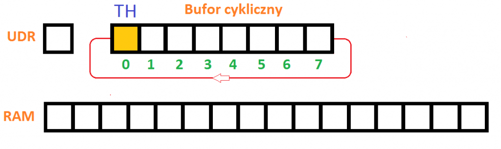
Rys. 1-1
Ogólny zarys bufora cyklicznego
Uwaga:
Każdy czarny kwadracik to pojedynczy bajt, czyli rejestr 8 bitowy. Bufor Cykliczny realizowany jest najczęściej przez program mikroprocesorowy.
Programista ma do dyspozycji np. mikrokontroler Atmega, a w nim 3 obszary pamięci:
– UDR – rejestr 1-bajtowy przyjmujący w dowolnych momentach pojedyncze bajty z zewnątrz
– Bufor Cykliczny – tu rejestr 8-bajtowy przyjmujący kolejne bajty z UDR-u.
Przeważnie rejestry są większe–> 16, 32 lub 64 bajtowe.
– RAM – Pamięć do której wprowadzane będą kolejne porcje bajtów z Bufora Cyklicznego, tu 8 bajtów.
W pracy systemu występują cykle składające się z 2 naprzemiennych etapów:
– Napełnianie Bufora Cyklicznego–>Kilka bajtów wpada z UDR do Bufora Cyklicznego
– Opróżnianie Bufora Cyklicznego–>Kilka bajtów wypada z Bufora Cyklicznego do pamięci RAM
Przesyłane bajty obracane są w Buforze Cyklicznym. Ruch bajtów w buforze przypomina węża z głową H (head) i z ogonem T (tail).
W głowie H jest zawsze najwcześniej wprowadzony z UDR bajt (najstarszy) , a ogonie T bajt najpóźniejszy (najmłodszy).
Rys 1-1 przedstawia stan początkowy Bufora Cyklicznego w którym H i T węża zajmują wspólnie bajt nr 0. Oznacza to brak węża albo innymi słowy, że bufor jest pusty. Po kilku cyklach cała informacja wprowadzona będzie z zewnątrz do pamięci RAM poprzez UDR i Bufor Cykliczny.
Nie wszystko zrozumiałeś? Nie martw się. Wszystko będzie jasne po animacji w następnym rozdziale.