Jak działa CRC?
Rozdział 8 A gdyby tak przesuwać o 8 bitów?
Rozdz. 8.1 Wstęp
Przekonasz się, że przesunięcia 8-bitowe są bardzo podobne do 2-bitowych z poprzedniego rozdziału. Przełożenie jest prawie 1:1 tzn. zamiast przesunięć 2-bitowych są 8-bitowe zaś samo CRC może mieć 8, 16 lub 32 bity. Tablicę 4x8 zastąpimy tablicą 256×8, 256×16 lub 256×32. Właśnie ze względu na ich duże rozmiary trudno jest realizować ich animację. Jednak dzięki analogii z przesunięciami 2-bitowymi, niepełna animacja przesunięć 8-bitowych którą zaproponuje, bez problemu pozwoli nam wyobrazić działanie systemu.
Rozdz. 8.2 Jakie jest CRC po przesunięciu 8-bitowym?
Jest to odpowiednik Rozdz. 7.3 Jakie jest CRC po przesunięciu 2-bitowym?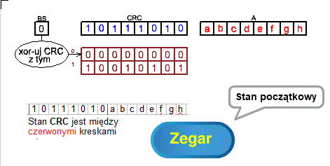
Rys. 8-1
Jakie jest CRC po przesunięciu 8-bitowym? ANIMACJA
W Rozdz. 7.3 badaliśmy stan 8-bitowego CRC po przesunięciu 2-bitowym dla wszystkich 4 możliwych kombinacji 2 początkowych stanów rejestru CRC: 00,01, 10 lub 11. Tu tymi kombinacjami będą 00000000, 00000001, 00000010….11111110 i 11111111. W sumie 256 kombinacji, czyli nasza tablica powinna mieć rozmiar 256×8.
No to zaczynamy wyznaczanie tych końcowych stanów. Dolny wiersz tablicy na Rys. 8-1 to 8 młodszych bitów “dzielnika”=1 10010101. Na jego podstawie będzie budowana tablica 256×8 dla przesunięć 8-bitowych.
Zaczynamy od najłatwiejszego stanu początkowego tj. 00000000. Jest oczywiste, że bity abcdefgh będą tylko przesunięto czyli ich stanem końcowym będzie abcdefgh inaczej abcdefgh xor 00000000.
W ten sposób wyznaczyliśmy pierwszy wiersz naszej tablicy=00000000.
A jak wyznaczyć wiersze dla pozostałych 255 kombinacji? Z oczywistych powodów nie będziemy tego robić i ograniczymy się tylko dla jednej kombinacji początkowej np. dla 10111010 czyli dla wiersza tablicy o numerze binarnym 10111010. W ten sam sposób można wyznaczyć pozostałe 254 wiersze tablicy.
Do stanu końcowego po 8 przesunięciach:
CRC=abcdefgh xor 00111000–>patrz Uwaga
czyli do wiersza o numerze binarnym 10111010 naszej tablicy możemy dojść na 2 sposoby:
– zaufać naszej maszynce w animacji, która działa zawsze tak samo jak dotychczas i po 8 kliknięciach dojść do stanu CRC=00111000
– rachunkowo tj. przesuwać czerwone kreski w prawo i xor-rować zawartość między czerwonymi kreskami przez:
–>00000000 gdy poprzednie BS=0
–>10010101 gdy poprzednie BS=1
Początkowe BS=1 jako pierwszy bit stanu początkowego CRC=10010101
Następne BS czyli next BS to xor kolumny przy lewej czerwonej kresce.
Uff! Brzmi to dosyć mętnie i skomplikowanie, ale najlepiej gdybyś sam do tego doszedł klikając zegar!
Uwaga:
00111000 to xor 8 wierszy miedzy czerwonymi kreskami które pojawią się na końcu animacji.
Rozdz. 8.3 CRC 32 bitowe z przesunięciem 8-bitowym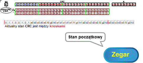
Rys. 8-2
CRC 32 bitowe z przesunięciem 8-bitowym ANIMACJA
Z Rozdz. 6 wiemy, że zdolność wykrywania błędów zależy od wielkości CRC. Powszechnie stosowane w internecie CRC 32-bitowe ma dużo większą moc wykrywania błędów niż CRC 8-bitowe. Skoki pozostają jednak 8-bitowe.
Generatorem naszego CRC (czyli “dzielnikiem” bez pierwszego bitu=1) jest dolny wiersz tablicy czyli:
generator=tablica(1)=01101100 10000001 00011101 10110111
Stan początkowy systemu to:
CRC=01100101 a0b0c0d0e0f0g0h0 a1b1c1d1e1f1g1h1 a2b2c2d2e2f2g2h2
oraz pierwszy bajt pamięci A “czekający” na przesunięcie 8-bitowe czyli A=a3b3c3d3e3f3g3h3
Używając bajtów i liczb hexa
65=01100101 C0=a0b0c0d0e0f0g0h0 C1=a1b1c1d1e1f1g1h1 C2=a2b2c2d2e2f2g2h2 C3=a3b3c3d3e3f3g3h3
możemy to zapisać bardziej zwięźle:
generator=tablica(1)=6C 81 1D B
Stan początkowy systemu to:
CRC=65 C0 C1 C2
A=C3
Jakie będzie CRC po 8 przesunięciach bitowych przy początkowym bajcie CRC=01100101 jak na Rys. 8-2?
Z animacji oraz niezależnie od tego z “xor-owania między czerwonymi kreskami” wynika, że będzie to:
CRC=C0 C1 C2 C3 xor D7 71 76 8C
gdzie:
D7 71 76 8C to 11010111 01110001 01110110 10001100
C0 C1 C2 C3 to patrz wyżej.
A to oznacza, że dla generator=6C 81 1D B7
tablica(65)=D7 71 76 8C
tablica(00)=00 00 00 00–>oczywista oczywistość bo BS=0 czyli są tylko przesunięcia!
W podobny sposób wyznaczymy pozostałe 254 wierszy tablicy o wymiarach 256×32.
Rozdz. 8.4 Metoda tablicowa bezpośrednia dla przesunięć 8-bitowych
Zanim zaczniesz badać system to wróć na chwilę do Rozdz. 7.3 i przypomnij sobie jak działa ta metoda dla przesunięć 2-bitowych.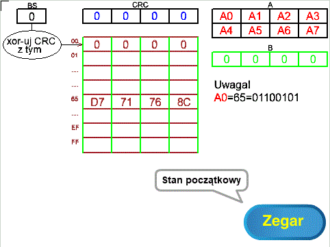
Rys. 8-3
Metoda tablicowa bezpośrednia dla przesunięć 8-bitowych ANIMACJA
Nawet Rys. 8-3 jest podobny do Rys. 7-3 z Rozdz. 7.3!
Analogie są następujące:
Rys. 7-3
– CRC jest 1-bajtowe
– pamięć A 2-bajtowa podzielona na 4 ćwierćbajty w każdym z 2 wierszy
– pierwszym ćwierćbajtem pierwszego wiersza pamięci A jest 10
– pamięć B jednobajtowa z 4 zerowymi ćwierćbajtami
– tablica 4 bajtowa z których każdy bajt podzielony jest na 4 ćwierćbajty
Rys. 8-4
– CRC jest 4-bajtowe
– pamięć A 8-bajtowa podzielona na 4 bajty w każdym z 2 wierszy
– pierwszym bajtem pierwszego wiersza pamięci A jest 0x65 czyli 011001010
– pamięć B 4-bajtowa z 4 zerowymi bajtami
– tablica 256×4 bajtowa w której każdy z 256 wierszy podzielony jest na 4 bajty
Z Rozdz. 8.3 wynika, że w tablicy po adresem:
– 0x00 jest 00 00 00 00 (4 zerowe bajty)
– 0x65 jest D7 71 76 8C
Pozostałe 254 4-bajtowe wiersze tablicy można oczywiście obliczyć, ale dałem sobie spokój.
Z animacji wynika, że przebiegi są podobne do z Rozdz. 7.4 tylko skoki są bajtowe, a nie ćwierćbajtowe. Animacja została zakończona na 7 impulsie zegarowym, potem wraca do stanu początkowego. Pierwsze 4 stany to zwykłe przesunięcia, bo BS=00. W piątym stanie następuje xor-owanie 4-bajtowego CRC zawartość wskazaną przez BS=65 czyli przez D7 71 76 8C. Dlatego bajty A1 A2 A3 i A4 rejestru CRC zmienią się na A1* A2* A3* A4*. Na tym animacja się kończy i wraca do stanu początkowego. Pozostałe stany animacji tj. 7 podwónych xor-owań przez zawartość tablicy wskazaną przez BS oraz “przepychanie” CRC 4 zerowymi bajtami musisz sobie wyobrazić korzystając z rozdz. 7.4. Pamiętaj tylko, że tu odpowiednikiem bajtów są ćwierćbajty czyli 2 bity.
Rozdz. 8.5 Metoda tablicowa „lewa” z podwójnym xor-owaniem dla przesunięć 8-bitowych
Wróć do Rozdz. 7.4 i przypomnij sobie jak działa ta metoda dla przesunięć 2-bitowych. Działania w obu metodach są podobne.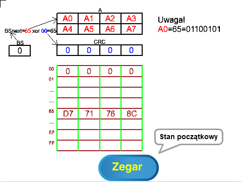
Rys. 8-4
Metoda tablicowa „lewa” z podwójnym xor-owaniem dla przesunięć 8-bitowych ANIMACJA
Rys. 8-4 jest podobny do Rys. 7-4 z Rozdz. 7.5!
W tej metodzie następna wartość bajtu BS czyli BSnext obliczana jest jako początkowy bajt A xor początkowy bajt CRC. Dzięki temu unikamy początkowego “pustego” przepychania wiadomości z A przez rejestr CRC oraz nie występuje zerowa 4-bajtowa pamięć B, która jak pamiętamy, była “przepychana” na końcu cyklu przez rejestr CRC.
Animacja przedstawia tylko stan początkowy oraz pierwsze “podwójne xor-owanie”. Pozostałe stany animacji tj. 7 “podwójnych xor-owań” musisz sobie wyobrazić korzystając z przesunięć 2-bitowych w rozdz. 7.5.
W odróżnieniu od metody bezpośredniej w rozdz. 8.4, wiadomość z A nie przechodzi szeregowo przez CRC, czyli początkowy bajt z A nie jest wprowadzany do najmłodszego bajtu CRC.
Rozdz. 8.6 Metoda tablicowa „prawa” z podwójnym xor-owaniem dla przesunięć 8-bitowych
Wróć do Rozdz. 7.6 i przypomnij sobie jak działa ta metoda dla przesunięć 2-bitowych. Działania w obu metodach są podobne.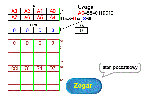
Rys. 8-5
Metoda tablicowa „prawa” z podwójnym xor-owaniem dla przesunięć 8-bitowych ANIMACJA
Rys. 8-5 jest podobny do Rys. 7-5 z Rozdz. 7.4! Główną zaletą metody “prawej” jest możliwość wysyłania bajtów do sieci w postaci jak najbardziej naturalnej. Tzn. takiej w której bit lewy jest starszy. Więcej na ten temat w rozdz. 7.6 w którym bit lewy w ćwierćbajcie jest starszy. Suma sumarum- bity w bajtach nie muszą być odwracane przed wysłaniem do sieci.
Aby tak było muszą być spełnione następujące warunki:
– bajty A0 A1 …A7 są ustawione w odwrotnych położeniach niż na Rys. 8-4 po to by były wysyłane w tej samej kolejności jak na Rys. 8-4
– bity w bajtach A0 A1 …A7 mają jednak tę samą kolejność jak na Rys. 8-4!
– 32 bity w tablicy są “obrócone” względem osi środkowej tablicy. W ten sposób np. 8 lewych bitów D7=11000111 w tablicy na Rys. 8-4 stają prawymi bitami “obróconymi” D7i=11100011. Uwaga ta dotyczy także bajtów 71 76 8C które też stają się “obróconymi” 71i 76i 8Ci.
– stan początkowy CRC też powinien być “obrócony”. Tu akurat nie ma to znaczenia bo stan początkowy jest zerowy. Ale może być też niezerowy i wtedy ma to znaczenie.
W animacji ujęte są tylko stan początkowy oraz pierwsze “podwójne xor-owanie”. Pozostałe stany animacji tj. 3 “podwójnych xor-owaia” musisz sobie wyobrazić korzystając z przesunięć 2-bitowych w rozdz. 7.6.
Rozdz. 8.7 Software czyli program obliczający CRC
Rozdział jest odpowiednikiem Rozdz.7.7. Jedyna różnica to przesunięcia bajtowe zamiast ćwierćbajtowych (dwubitowych). Wystarczy w instrukcjach zamienić wyrażenie “2 bity” na “8 bitów”. Pamiętaj też o tym, że tablice mają inne rozmiary.
Rozdz. 8.7.1 Program dla metody tablicowej bezpośredniej z przesunięciami 8-bitowymi
Rejestry BS CRC A B z Rys.8-3 tworzą wspólny rejestr przesuwny BS_CRC_A_B. Instrukcja Wpisz 8 bitów z A do CRC w lewo naszego pseudojęzyka, wpisuje nie tylko 8 początkowych bitów z A do CRC, ale przesuwa też cały rejestr BS_CRC_A_B o 8 bitów w lewo. Następnie CRC jest xor-owane przez wiersz tablicy wskazany przez BS.
Program w pseudojęzyku
Wpisz wiadomość do A
Wpisz zera do B
Dopóki A niepuste
{ Wpisz 8 bitów z A do CRC w lewo
CRC=CRC xor tablica(BS) }
Po wyjściu z pętli CRC będzie zawierało obliczoną “resztę”.
Rozdz. 8.7.2 Program dla metody tablicowej “lewej” z podwójnym xor-owaniem i przesunięciami 8-bitowymi
Nie ma zerowego bajtu B. Wspólny rejestr przesuwny w lewo tworzą tylko BS_A. Czyli A nie przechodzi przez CRC jak w poprzednim przykładzie, ale samo CRC też jest oczywiście przesuwane o 8 bitów w lewo.
Po każdym 8-bitowym przesunięciu w lewo wspólnego rejestru BS_A, obliczane jest BS:
BS=8 początkowych bitów A xor 8 początkowych bitów CRC.
Następnie CRC jest xor-owane przez wiersz tablicy wskazany przez BS.
Program w pseudojęzyku
Wpisz wiadomość do A
Dopóki A niepuste
{ Przesuń BS_A o 8 bitów w lewo
BS=8 początkowych bitów A xor 8 początkowych bitów CRC
CRC=CRC xor tablica(BS) }
Po wyjściu z pętli CRC będzie zawierało obliczoną “resztę”.
Rozdz. 8.7.3 Program dla metody tablicowej “prawej” z podwójnym xor-owaniem i przesunięciami 8-bitowymi
Program różni się od poprzedniego tylko przesunięciem w prawo. Pamiętaj jednak o uwagach dotyczących tablicy i CRC pod Rys. 8-5! Także bajty w A są “obrócone” względem środkowej osi, ale bity w bajtach już nie!
Dzięki temu programista nie musi “obracać” każdego bajtu przed wysłaniem go do UART-u.
Program w pseudojęzyku
Wpisz wiadomość do A
Dopóki A niepuste
{ Przesuń BS_A o 8 bitów w prawo
BS=8 początkowych bitów A xor 8 początkowych bitów CRC
CRC=CRC xor tablica(BS) }
Obróć CRC
Po wyjściu z pętli należy jeszcze obrócić CRC.