How does CRC work?
Chapter 7 What if we shifted by 2 bits?
Chapter 7.1 Introduction
We know from the previous chapter that the actual CRC register is 1, 2, or 4 bytes long. And what else is it different from the one in chapter 5? First of all, shifts. In earlier chapters they were bit-based, and the ones commonly used by programmers are byte-based. Usually, when a program wants to send e.g. 100 bytes, it enters them byte by byte into the so-called UART, which itself sends them bit by bit to the network. And how it does this is the job of a UART-type chip designed by some guy several dozen years ago. This means that the program sending 1 byte must also calculate the CRC state after 8 bit shifts! The first thing that comes to mind is a program that performed 8 one-bit shifts according to: Chapter 5.2. This is rather a time-consuming and transmission-delaying SIMPLE method that is not used in practice. This disadvantage does not have the commonly used so-called array methods. Unfortunately, the large dimensions of these boards, 256×8 and even 256×32, make it difficult to understand the principle of operation. Therefore, we will first learn about CRC methods for 2-bit shifts. The boards here are small in size 4×8 and are easier to analyze. Then you will easily understand in Chapter. 8 “real” array CRC methods.
Chapter 7.2 Single Byte CRC Calculator with 1-bit Shift
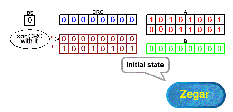
Fig. 7-1
Single Byte Bit Shift CRC Calculator ANIMATION
This is a version of the system that is more close to reality in Chapter 5.2. Instead of a 4-bit CRC, we have an 8-bit one and instead of 1 byte of transmitted information (or “divisive”), there are 2 bytes in the A register. In real networked systems (and not just in this course), there can be thousands of these bytes in register A, not just 2! The “divisor” is 1 10010101, of which the 8 lower bits are, as usual, placed at address 1 in a 2×8 array. We see that the CRC calculation method we have learned so far is also an array! And with a pretty serious 2×8 array!
Click on the animation and see how CRC is calculated using the current bit-by-bit method, i.e. SIMPLE method. The next examples in this chapter will be a modification of it with a 2-bit shift and an 8-bit shift in Chapter 8. In this chapter, “Divisible“, i.e. the information sent, and “Divisor” will be the same in all animations. So the final result should always be CRC=11100110.
However, in Chapter 7.6 is a different CRC and I don’t know why! I’m counting on readers’ help here.
Chapter 7.3 What is the CRC after a 2-bit shift?
Chapter 7.3.1 Introduction
We already know what the CRC state will be after a 1-bit shift. So we can also predict the state after the next 1-bit shift, i.e. after a total of 2 bit shifts. Therefore, we will examine the CRC after a 2-bit shift for all possible combinations of the 2 bits of the initial CRC registers, i.e. 00, 01, 10 and 11.
Chapter 7.3.2 CRC with 2-bit shift when the first 2 bits are 00
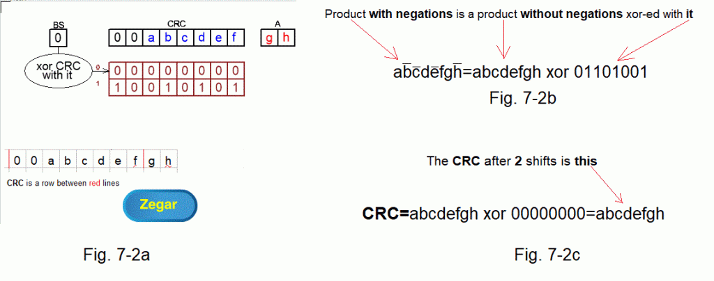
Fig. 7-2
The initial state when the first 2 CRC bits are 00 ANIMATION
In this case, the matter is trivial. The abcdefgh bits will only be shifted because after each shift BS=0.
This means that the CRC will be xor-ed with a zero value and this operation changes nothing.
Fig. 7-2a shows the initial state of the CRC as the bits between the red lines. The animation shows that operations on registers are accompanied by appropriate xorizations with zero lines, the result of which is the xorization of all lines between the red lines.
Fig. 7-2b shows the principle that any logical product with negations can be represented as a product without negation xor-ed with the appropriate bit number. This number has bit=1 in the position where the product has a negated (“capped”) value. Remember this rule!
Fig. 7-2c shows the CRC status after 2 shifts as CRC=abcdefgh xor 00000000.
Ch. 7.3.3 CRC with 2-bit shift when the first 2 bits are 01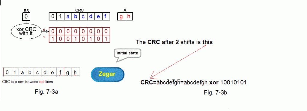
Fig. 7-3
The initial state when the first 2 bits of the CRC are 01 ANIMATION
In Chapter 7.3.2 predicting the CRC state was trivial because there were only shifts. Now the initial state is CRC=01abcdef. The gh bits are waiting in memory A. The remaining bits of memory A are of no interest to us for obvious reasons. After all, they will not affect the CRC status after 2 shifts.
Now the state of BS=1 will appear and it won’t be so nice. You can predict the state after 2 shifts using 2 methods:
1. Using animation. And since you know the rules, you are able to do it “in your head”.
2. By the calculating method, i.e. “in your head”. Figure it out yourself using animations. If this fails, the method is as follows:
– Write 01abcdefgh. Separate the initial state of the CRC register, i.e. 01abcdef, with red lines as in Fig. 7-3a. Next BS=0 because the first CRC bit is 0
– Write the shifted 00000000 above the initial state because BS=0. Now the new CRC state is xor 2 lines between the red lines. You don’t have to calculate it for now, but check for your own satisfaction whether it is like in the animation. Next BS=1 as the xor of the first column between the red lines
– Write the shifted 10010101 because BS=1. The new and final state of the CRC is xor 3 lines between the red lines, i.e. CRC=abcdefgh xor 10010101 as in Fig. 7-3b
After 2 shifts, CRC=abcdefgh xor 10010101.
Comments:
– In the CRC formula, the value 10010101 after the xor symbol is the xor 2 lines above abcdefgh after the second shift
– After the second shift, “hats” appeared over the symbols a, d, f and h –>Fig. 7-3b, which means that these values have been negated.
Chapter 7.3.4 CRC with 2-bit shift when the first 2 bits are 10

Fig. 7-4
The initial state when the first 2 CRC bits are 10 ANIMATION
After 2 shifts, CRC=abcdefgh xor 10111111.
Ch. 7.3.5 CRC with 2-bit shift when the first 2 bits are 11

Fig. 7-5
The initial state when the first 2 CRC bits are 11 ANIMATION
After 2 shifts, CRC=abcdefgh xor 00101010
Chapter 7.3.6 Table as a summary of this chapter
The above subchapters show that knowing the 2 starting bits of the CRC, we can immediately calculate its new state after the shifts using appropriate xorings.
When the first 2 bits:
– 00 is the next CRC=CRC xor 00000000
– 01 is the next CRC=CRC xor 10010101
– 10 is the next CRC=CRC xor 10111111
– 11 is the next CRC=CRC xor 00101010
This corresponds to a 4×8 array with 4 addresses 00, 01, 10 and 11 in Fig. 7-6. The current state of the 2-bit BS register indicates the line through which the CRC should be xored to hold the new state after the 2-bit shift. There is some analogy here to Fig. 7-1 with a 1-bit shift and a 2-row array.
Chapter 7.4 Direct array method for 2-bit shifts
First, about the method name I proposed. Array-because it uses arrays, just like the 1-bit shift method, e.g. in Fig. 7-1. And direct? Because it is based on the arithmetic from Chapter 4.4 with the addition of zeros and its register implementation in Fig. 7-1. Another justification may be single xoring, and not double as in chapters 7.5 and 7.6.
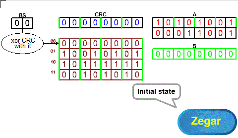
Fig. 7-6
Direct array method for 2-bit shifts ANIMATION
A 2-byte message from register A passes through the CRC register in 2-bit steps. Finally, a byte with zeros from the B register is transferred in the same way. I would like to remind you that the BS, CRC, A, B registers can be treated as one common register BS_CRC_A_B in which the data is shifted by 2 bits to the left in each clock pulse. Each shift is accompanied by xoring of the data from the CRC with the data indicated by the BS. Even if BS=00, this is also xoring, but this operation does not change anything.
In chapter 8, you will find that these actions closely resemble 8-bit shifts. Except that 2 bits correspond perfectly to 8 bits and the “ratio” is almost 1:1. And why “almost”? Because the array will have 256 addresses as an 8-bit BS gives 256 different bit combinations.
Chapter 7.5 “Left” array method with double xoring for 2-bit shifts
Array – you know, “left” because the bits shift to the left, and “double xoring” you will know in a moment.
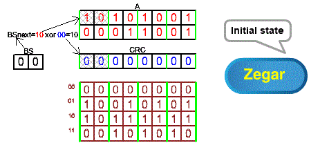
Fig. 7-7
Double-xored “left” array method for 2-bit shifts ANIMATION
In the direct method, 2 bits directly passed from CRC to BS. Here they also go from CRC to BS but are additionally xor-ed with the initial 2 bits from memory A. Message A bypasses the CRC here, otherwise it does not go through the CRC. Note that thanks to this principle, the B register with zeros and the initial “empty” trace with zeros disappear as in Chapter. 7.4. This is probably “elegant”, although at the cost of additional CRC xoring through the data from message A. I have mixed feelings here. After all, register A is in practice thousands of bytes. This means that the “empty” trace and the B register have no effect on the transmission. Perhaps this additional xoring occurs in the same cycle as the single xoring from Chapter 7.4 and therefore does not affect the transmission speed. And this is probably the case, because the direct method is not used in practice, or is used less often. In the animation you will see that the calculated final CRC=11100110 is of course the same as in Chapter 7.2 and 7.4!
Chapter 7.6 Double-xored “right” array method for 2-bit shifts
The name speaks for itself.

Fig. 7-8
“Right” double-xored array method for 2-bit shifts ANIMATION
What’s the point if the previous method seems to be unchallenged? Return for a moment to Chapter 7.1. It was mentioned that all bits going outside, i.e. to the network, pass through the so-called UART. And this one most often (or maybe always?) treats the right bits as more significant. So, for example, byte = 00000001 will be treated as 128, and byte = 10000000 as 1. The opposite of what we are used to. Too bad, these UARTs were designed about 50 years ago and there’s nothing we can do about it. And we want 00000001 to be treated as 1. For example, you can modify the “left” method to “rotate” each byte before sending and everything will be OK. It turns out that, first of all, not every microprocessor has such a simple, seemingly simple command. And secondly, if you already have it, it takes some time to make it. And this delays the transmission! And that’s what the “right” method is for. Here, the data of the entered quarter byte is “human”, i.e. the left bit is more important than the right one. In the initial state in Fig. 7-7, the first quarter byte introduced to the network and to the BS modifying the CRC is 10, i.e. 2, not 1! So the entire byte with A=01101010 will be treated by UART as 10101001 from Chapter 7.5. And that’s what we wanted!
But three additional conditions must be met:
1. All rows in the array must be “rotated” about the central axis.
2. The initial state of the CRC register must also be “rotated”.
3. The calculated final CRC is also “rotated”.
ad. 1, for example, line 3 11111101 is “rotated” relative to line 3 10111111 from Chapter 7.5
ad. 2 here the initial CRC=00000000 is “rotated” relative to CRC=00000000 from Chapter7.5. In the case of
zero CRC, “rotating” changes nothing, but there are CRC algorithms that have a non-zero starting CRC.
Make an animation and you will see that the calculated CRC will be the same as in Chapters 7.2 and 7.4, i.e. CRC=11100110. After all, the input messages A=10101001 00011001 are the same, and the arrays in Chapter 7.4 and 7.5 were built on the same base–>“divisor”=10010101 from Chapter 7.2!
But nothing like that!! CRC=10010101 is different than in Chapter 7.2 and 7.4. And this is the original sin of this course. Now I’m counting on help from readers smarter than me. I give the first person who points out the error and calculates with the “right” method that CRC=11100110 an eight-pack of good beer! Please just send your bank account number by email. It’s not a Nobel Prize, but this one had a bit more potential.
Chapter 7.7 Software, i.e. a program that calculates CRC
Chapter 7.7.1 Introduction
The message to be sent is in register A. The arrays were created based on Chapter 7.4, except that the “right” array (chapter 7.6) is slightly different than the “left” and “direct” arrays. I leave the array building programs themselves to more ambitious readers. A kind of pseudo-language is used that requires almost no comment.
Chapter 7.7.2 Program for the direct array method with 2-bit shifts
The BS CRC A B registers in Fig.7-6 form the common shift register BS_CRC_A_B. The Write 2 bits from A to CRC left instruction of our pseudo-language not only writes the initial 2 bits from A to CRC, but also shifts the entire BS_CRC_A_B register 2 bits to the left. The CRC is then xor-ed by the array row pointed to by the BS.
B=0
As long as A is not empty
{ Write 2 bits from A to CRC to the left
CRC=CRC xor array(BS) }
After exiting the loop, the CRC will contain the calculated “remainder” that is the CRC.
Chapter 7.7.3 Program for the “left” array method with double xoring and 2-bit shifts
There is no “zero” B register
As long as A is not empty
{
BS=2 starting bits A xor 2 starting CRC bits
Shift A 2 bits to the left
Shift CRC 2 bits to the left
CRC=CRC xor array(BS)
}
After exiting the loop, the CRC will contain the calculated CRC or “remainder“.
Chapter 7.7.4 Program for the “right” array method with double xoring and 2-bit shifts
Remember the notes regarding the array and CRC in Chapter. 7.6! Especially since the quarter bytes in A are “rotated”, but the bits in the quarter bytes are not! This saves the programmer from having to “rotate” each quarter byte before sending it to the UART.
As long as A is not empty
{
BS=2 starting bits A xor 2 starting CRC bits
Shift A 2 bits to the right
Shift CRC 2 bits to the right
CRC=CRC xor array(BS)
}
Rotate CRC
After exiting the loop, the CRC will contain the calculated CRC or “rest”.
