How does CRC work?
Chapter 5 Calculating CRC on registers
Chapter 5.1 Introduction
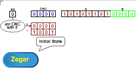
You already know how to calculate CRC and it is much easier than simple decimal division. The algorithm is only shifts and possibly xor-ing. They can therefore be easily implemented on shift registers supported by simple logic based on xoring.ig. 5-1
Chapter 5.2 CRC Calculation System

Rys. 5-1
CRC Calculation System ANIMATION
The system consists of “left” shift registers BS CRC A B and a 2×4 table register used to modify the CRC after the shift. This is an electronic implementation of calculating the “remainder” of the “division” 10101101:11001 i.e. the arithmetic of which is described in Chapter 4.4. I would like to remind you that the A register contains the “divisive“, i.e. transmitted message. It can be of any length. Enter the animation and figure out the action yourself. For your convenience, each state of CRC calculation is shown. But honestly, you can ignore it.
Each clock pulse (“zegar”) shifts the contents of the BS CRC A B registers to the left.
The divider 11001, or more precisely, only its 4 lower bits 1001, is placed in the 2-element ROM permanent memory at address 1.
At address 0 there is 0000.
After each shift, the xor operation is performed:
When BS=1 then CRC=CRC xor 1001
When BS=0, CRC=CRC xor 0000, i.e. CRC is only shifted
The CRC is finally calculated when the A and B registers are empty.
Experiment until everything is clear to you.
Note:
The animation here is very precise, i.e. the shifting and xoring stages are separated. In the next course examples they are already
only one common stage, which is, however, somewhat difficult. Therefore, I appeal to you to thoroughly understand the principle of operation so as not to go into details that are already understandable later.
Chapter 5.3 Shift register with linear feedback
Otherwise known as LFSR Linear-Feedback Shift Register
This is a different implementation of the system from Chapter 5.2
Where does this name come from? Shift register because it shifts. Feedback because the signal in the register reverses. And linear?
Let it be like a old riddle.
What is this? It hangs on the wall, green and singing.
It’s obvious that a herring.
He hangs because they hanged him
Green because they painted it
And he sings to make it harder to guess.
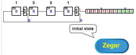
But seriously. This is a shift register in which the state D3 D2 D1 D0 is a linear function of the previous state D3 D2 D1 D0. And the linear function is xor. And why is xor a linear function? Let’s give it a rest here.

Fig. 5-2
CRC Calculation System as LFSR ANIMATION
How to build an LFSR?
1. Write all the bits of the “divisor” except the highest one. Here 1001 because the “divisor” is 11001
2. Under each digit 1001, place a D-flip-flop-memory element (you placed D3 D2 D1 D0)
3. Place an XOR gate behind each flip-flop that has a 1 above it
4. Connect everything as in Fig. 5-2
This is how you designed the LFSR register. Enter the animation and after subsequent clicks – clock pulses, the LFSR register will calculate the “remainder of division” 10101101, i.e. the number located in register A. That is, LFSR calculates the CRC from the message located in register A of any length – usually a multiple of a byte.
Similarly, you build registers for other than 1001 “dividers”.
The beginning of the animation is easy, because the “lower” xor inputs are 0. The data is only moved. Then, this pleasant analysis is disturbed by 1 states that may appear at the inputs of the xors.
Note that the animation comments in the clouds of that make it easier to analyze the action are in the future:
– I’ll just move it because D3=0
– I will shift and xor because D3=1
Try to predict the next state D3 D2 D1 D0 after clicking the clock.
Chapter 5.4 Transmitter-Receiver transmission example
There is an implementation of the algorithm from Chapter 4.4 when we add 0000 to the dividend

Fig. 5-3
Transmitter-Receiver Transmission ANIMATION
Our goals are to transfer information from the RN in the transmitter to the RO in the receiver. In addition, the receiver must know that most likely there were no errors during transmission. For this purpose, there are CRC-N and CRC-O registers in the transmitter and receiver, which calculate the CRC independently of each other. It can be implemented as CRC, BS and ROM (Read Only Memory) of Fig. 5-1 or LFSR of Fig. 5-2. By the way. Messages such as RN–>CRC-N or RN–>CRC-0 appear in the animation clouds. However, this is not a simple transfer, but a transfer plus calculation of a new CRC as in Fig. 5-1 or Fig. 5-2!
Stage 1 RN–>RO transmission + CRC calculation in CRC-N and CRC-O.
Step 2 completes the CRC calculation in CRC-N and CRC-O (“pushing” 0000 into these registers).
Stage 3 CRC-N –> CRC-O transmission and their comparison. If they are the same, the transmission is correct.
Note
In a real transmission, the message being sent, i.e. the content of the RN, can be thousands of bytes long!
Chapter 5.5 Example of Transmitter-Receiver transmission “with the remainder added”
There is an implementation of the algorithm from Chapter 4.5 when we add 1001 to the dividend, i.e. the final remainder
Fig. 5-4
Transmitter-Receiver transmission “with the rest added” ANIMATION
Weird? Register B=0000 and it should be B=1001 because this is the rest added! What’s more, the drawing is the same as Fig. 5-3! The matter is obvious. Stage 1 is exactly the same as in the previous chapter. In the initial state B =0000 because the transmitter does not yet know what the CRC is. Until these zeros “reach” CRC-N and CRC-0, they have no effect on CRC-N and CRC-0. At the end of stage 1, the receiver will remember the CRC-state O in the copy register in order to “remember” it at the end of stage 2. You will see the copy register in the animation. The algorithm will continue as in Chapter 4.5, as if it had been B=1001 from the very beginning. The final state will be CRC-O=0000 , i.e. the transmission was error-free.
Chapter 5.6 Software, i.e. a program that calculates CRC
If you are not a programmer, you can skip this chapter. But at least try
The program is written in a pseudo-language that is understandable to everyone. The reader-programmer can easily replace it with his favorite language, e.g. C or assembler. This note also applies to the following chapters.
The BS CRC A B registers in Fig. 5-1 form the common shift register BS_CRC_A_B. The Write A to CRC Left instruction of our pseudo-language not only writes the initial bit from A to the CRC, but also shifts the entire BS_CRC_A_B register by 1 bit to the left. After each shift, the one-bit BS register is examined and the CRC is xor-ed with the table row pointed to by the BS. After entering the last bit from A to the CRC, register A is empty and this means that the program ends. Then the CRC contains the calculated remainder.
Table memory description:
Array(0)=0000
Array(1)=1001=generator i.e. all the “divisor” bits except the oldest one.
In our case, also concerning chapter 4.4, “divisor”=1 1001 i.e. generator=1001.
A program in a pseudo-language
Write a message to A
Put zeros in B
Until CRC is not empty
{ Write A into CRC left
CRC=CRC xor array(BS) }
For BS=0 we have CRC=CRC xor array(BS=0)=CRCxor0000=CRC so there is only an byte move.
Therefore, the program can also be presented in the equivalent form:
Write a message to A
Put zeros in B
Until CRC is not empty
{ Enter A into CRC
if BS=1 then CRC=CRC xor generator }
This version is probably even more clear.
The program will end when it exits the loop.
Then all bits A B will go through the CRC and A will become “empty”*. This means that the CRC contains the calculated “remainder”.
*Note “Empty” A that’s not necessarily 0000! They’re just bits that don’t matter to us anymore.
