How does CRC work?
Chapter 8 What if we shifted by 8 bits?
Chapter 8.1 Introduction
You will find that 8-bit shifts are very similar to the 2-bit shifts from the previous chapter. The ratio is almost 1:1, i.e. instead of 2-bit shifts, they are 8-bit, and the CRC itself can be 8, 16 or 32 bits. We will replace the 4×8 array with a 256×8, 256×16 or 256×32 array. Due to their large size, it is difficult to animate them. However, thanks to the analogy with 2-bit shifts, the incomplete animation of 8-bit shifts that I will propose will easily allow us to imagine how the system works.
Chapter 8.2 What is the CRC after an 8-bit shift?
This is equivalent to Chapter 7.3 What is the CRC after a 2-bit shift
Fig. 8-1
What is the CRC after an 8-bit shift? ANIMATION
In Chapter 7.3 we examined the state of the 8-bit CRC after a 2-bit shift for all 4 possible combinations of the 2 initial states of the CRC register: 00.01, 10 or 11. Here these combinations will be 00000000, 00000001, 00000010….11111110 and 11111111. In total 256 combinations, so our array should have a size of 256×8.
So let’s start determining these final states. The bottom line of the array in Fig. 8-1 is the 8 lower bits of the “divisor”=1 10010101. On its basis, a 256×8 array for 8-bit shifts will be built.
We start with the easiest initial state, i.e. 00000000. It is obvious that the abcdefgh bits will only be shifted, i.e. their final state will be abcdefgh, otherwise abcdefgh xor 00000000.
This way we have designated the first row of our array=00000000.
And how to determine the rows for the remaining 255 combinations? For obvious reasons, we will not do this and will limit ourselves to only one initial combination, e.g. 10111010, i.e. for the array row with the binary number 10111010. The remaining 254 array rows can be determined in the same way.
To the final state after 8 shifts:
CRC=abcdefgh xor 00111000–>see Note
that is, we can get to the line with the binary number 10111010 of our array in two ways:
– trust our animation machine, which always works the same as before and after 8 clicks we will reach the state CRC=00111000
– numerically, i.e. move the red lines to the right and xor-row the content between the red lines by:
–>00000000 when previous BS=0
–>10010101 when previous BS=1
Initial BS=1 as the first bit of the initial state CRC=10010101
Next BS is the xor of the column at the left red line.
Phew! It sounds quite confusing and complicated, but it’s best if you figure it out yourself by clicking on the clock!
Note:
00111000 is xor 8 lines between the red lines that will appear at the end of the animation.
Chapter 8.3 32-bit CRC with 8-bit shift
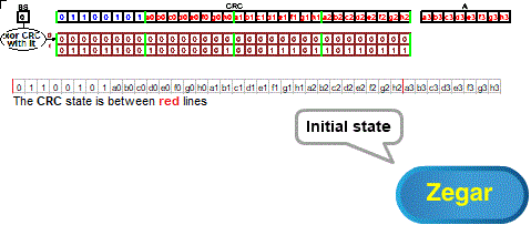
Fig. 8-2
32 bit CRC with 8 bit shift ANIMATION
From Chapter 6, we know that the error detection ability depends on the size of the CRC. Commonly used on the Internet, 32-bit CRC has much greater error detection power than 8-bit CRC. Shifts, however, remain 8-bit.
The generator of our CRC (i.e. the “divisor” without the first bit=1) is the bottom row of the array, i.e.:
generator=array(1)=01101100 10000001 00011101 10110111
The initial state of the system is:
CRC=01100101 a0b0c0d0e0f0g0h0 a1b1c1d1e1f1g1h1 a2b2c2d2e2f2g2h2
and the first byte of memory A “waiting” for an 8-bit shift, i.e. A=a3b3c3d3e3f3g3h3
Using bytes and hex numbers
65=01100101 C0=a0b0c0d0e0f0g0h0 C1=a1b1c1d1e1f1g1h1 C2=a2b2c2d2e2f2g2h2 C3=a3b3c3d3e3f3g3h3
we can write it more concisely:
generator=array(1)=6C 81 1D B
The initial state of the system is:
CRC=65 C0 C1 C2
A=C3
What will be the CRC after 8 bit shifts with the starting byte CRC=01100101 as in Fig. 8-2?
From the animation and independently from the “xoring“ between red lines” it follows that it will be:
CRC=C0 C1 C2 C3 xor D7 71 76 8C
Where:
D7 71 76 8C is 11010111 01110001 01110110 10001100
C0 C1 C2 C3 then see above.
And this means that for generator=6C 81 1D B7
array(65)=D7 71 76 8C
array(00)=00 00 00 00–>obvious because BS=0, so there are only shifts!
In a similar way, we will determine the remaining 254 rows of the 256×32 array.
Chapter 8.4 Direct array method for 8-bit shifts
Before you start examining the system, go back to Chapter 7.3 and recall how this method works for 2-bit shifts.
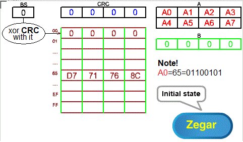
Fig. 8-3
Direct array method for 8-bit shifts ANIMATION
Even Fig. 8-3 is similar to Fig. 7-3 from Chapter 7.3!
The analogies are as follows:
Fig. 7-3
– CRC is 1 byte
– 2 byte A memory divided into 4 quarter bytes in each of 2 lines
– the first quarter byte of the first line of memory A is 10
– single-byte B memory with 4 zero quarter bytes
– 4 byte array, each byte divided into 4 quarter-bytes
Fig. 8-4
– CRC is 4 bytes
– 8-byte A memory divided into 4 bytes in each of 2 lines
– the first byte of the first line of memory A is 0x65, i.e. 011001010
– 4 byte B memory with 4 zero bytes
– 256×4 byte array in which each of the 256 lines is divided into 4 bytes
From Chapter 8.3 shows that in the array at address:
– 0x00 is 00 00 00 00 (4 zero bytes)
– 0x65 is D7 71 76 8C
The remaining 254 4 byte rows of the array can of course be calculated, but I gave up.
The animation shows that the waveforms are similar to those in Chapter 7.4 only shifts are byte, not quarter byte. The animation finished on the 7th clock pulse, then returns to the initial state. The first 4 states are simple shifts because BS=00. In the fifth state, the 4-byte CRC is xored, the content indicated by BS=65, i.e. by D7 71 76 8C. Therefore, bytes A1 A2 A3 and A4 of the CRC register will change to A1* A2* A3* A4*. This is where the animation ends and returns to its initial state. The remaining states of the animation, i.e. 7 double xors through the contents of the table indicated by BS and “pushing” the CRC with 4 zero bytes, you must imagine using chapter 7.4. Just remember that the equivalent of bytes here are quarterbytes, i.e. 2 bits.
Chapter 8.5 Left-hand double-xored array method for 8-bit shifts
Return to Chapter 7.4 and recall how this method works for 2-bit shifts. The operations in both methods are similar.
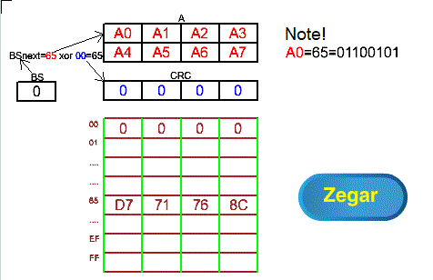
Fig. 8-4
“Left” double-xored array method for 8-bit shifts ANIMATION
Fig. 8-4 is similar to Fig. 7-4 from Chapter 7.5!
In this method, the next BS byte value i.e. BSnext is calculated as the starting A byte xor the starting CRC byte. This avoids the initial “empty” pushing of messages from A through the CRC register, and there is no zero 4-byte B memory, which we remember was “pushed” at the end of the cycle by the CRC register.
The animation shows only the initial state and the first “double xoring”. You must imagine the remaining animation states, i.e. 7 “double xor-ings”, using 2-bit shifts in chapter 7.5.
Unlike the direct method in Chapter 8.4, the message from A does not pass through the CRC serially, i.e. the starting byte from A is not inserted into the lowest byte of the CRC.
Chapter 8.6 Double-xored “right” array method for 8-bit shifts
Return to Chapter 7.6 and recall how this method works for 2-bit shifts. The operations in both methods are similar.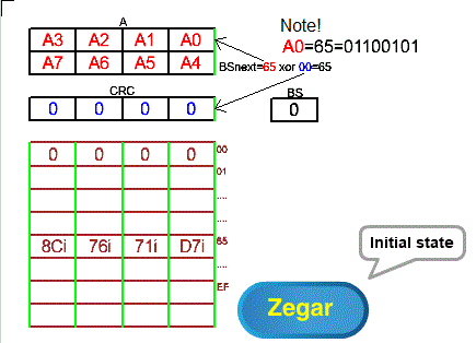
Fig. 8-5
Double-xored “right” array method for 8-bit shifts ANIMATION
Fig. 8-5 is similar to Fig. 7-5 from Chapter 7.4! The main advantage of the “right” method is the ability to send bytes to the network in the most natural form possible. I.e. one in which the left bit is higher. More on this topic in chapter 7.6 in which the left bit in the quarter byte is higher. Sum sumarum- bits in bytes do not need to be reversed before being sent to the network.
For this to happen in the “right” method, the following conditions must be met:
– bytes A0 A1 …A7 are set in the opposite positions than in Fig. 8-4 so that they are sent in the same order as in Fig. 8-4
– the bits in bytes A0 A1 …A7, however, have the same order as in Fig. 8-4!
– 32 bits in the array are “rotated” relative to the center axis of the array. In this way, for example, the 8 left bits D7=11000111 in the array in Fig. 8-4 become the right “rotated” bits D7i=11100011. This note also applies to bytes 71 76 8C which also become “rotated” 71i 76i 8Ci.
– the initial state of the CRC should also be “rotated”. It doesn’t matter here because the initial state is zero. But it can also be non-zero and then it matters.
Only the initial state and the first “double xoring” are included in the animation. You must imagine the remaining animation states, i.e. 3 “double xoring“ using 2-bit shifts in chapter 7.6.
Chapter 8.7 Software, i.e. a program that calculates CRC
This chapter is equivalent to Chapter 7.7. The only difference is byte shifts instead of quarter-byte (two-bit) shifts. Just replace the expression “2 bits” with “8 bits” in the instructions. Also remember that the arrays have different sizes.
Chapter 8.7.1 Program for the direct array method with 8-bit shifts
The BS CRC A B registers in Fig.8-3 form the common shift register BS_CRC_A_B. The Write 8 bits from A to CRC left instruction of our pseudo-language not only writes the initial 8 bits from A to CRC, but also shifts the entire BS_CRC_A_B register 8 bits to the left. The CRC is then xored by the array row pointed to by the BS.
A program in a pseudo-language
Write a message to A
Put zeros in B
As long as A is not empty
{ Write 8 bits from A to CRC to the left
CRC=CRC xor array(BS) }
After exiting the loop, the CRC will contain the calculated “remainder”.
Chapter 8.7.2 Program for the “left” array method with double xoring and 8-bit shifts
There is no zero B byte. The common left shift register is formed only by BS_A. So A does not pass through CRC as in the previous example, but the CRC itself is also, of course, shifted 8 bits to the left.
After each 8-bit left shift of the common register BS_A, the BS is calculated:
BS=8 starting bits A xor 8 starting CRC bits.
The CRC is then xor-ed by the array row pointed to by the BS.
A program in a pseudo-language
Write a message to A
As long as A is not empty
{ Shift BS_A 8 bits left
BS=8 starting bits A xor 8 starting CRC bits
CRC=CRC xor array(BS) }
After exiting the loop, the CRC will contain the calculated “remainder”.
Chapter 8.7.3 Program for the “right” array method with double xoring and 8-bit shifts
The program differs from the previous one only by shifting to the right. However, remember the notes regarding the array and CRC in Fig. 8-5! Also the bytes in A are “rotated” about the central axis, but the bits in the bytes are not! This saves the programmer from having to “rotate” each byte before sending it to the UART.
A program in a pseudo-language
Write a message to A
As long as A is not empty
{ Shift BS_A 8 bits to the right
BS=8 starting bits A xor 8 starting CRC bits
CRC=CRC xor array(BS) }
Rotate CRC
After exiting the loop, you need to rotate the CRC again.