Complex Numbers
Chapter 4 Complex numbers in electrical engineering
Chapter 4.1 Introduction
The calculation of alternating currents and voltages is a mathematical operation on sine waves. There is no problem when the electrical circuit consists only of resistances. Then the current sine wave is in phase with the voltage sine wave. You only need to calculate the current amplitude by DC methods. Some Kirchoffs, Thevenins, Nortons, etc…
The introduction of inductance L or capacitance C into the electric circuit changes not only the current amplitude but also shifts its sine wave by the appropriate angle-phase φ. The trick is to calculate the amplitude and phase of the current. This can be done using trigonometry, but very complicated formulas result! Meanwhile, complex numbers make calculus much easier.
Chapter 4.2 The complex function exp(jωt) as a rotating vector
Complex numbers are very much related to the sine wave, or harmonic motion. Alternating currents are sine waves. Therefore, it is not surprising that complex numbers appeared first in mathematics, which is obvious, but then in electrical engineering of the 19th century, together with alternating currents. Sine waves are treated by electricians as rotating vectors, or what is almost the same as complex numbers. For more on this, see 3.1. Fourier Series, Chapter.
Chapter 4.3 RL Circuit
Let’s consider a simple example with resistance and inductance, i.e. with the RL circuit. What are the specific values of R and L? Never mind. Only the time charts with these parameters on the oscilloscope is important – Fig. 4-1b. The phase shift φ=π/6=30º appears.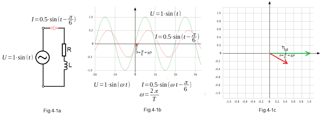
Fig. 4-1
RL circuit with a variable voltage input
Fig. 4-1a
– input sinusoidal voltage U=1sin(1t) in volts
–output sinusoidal current I=0.5sin(1t-30º) in amperes.
Fig. 4-1b
Time charts
The waveforms here are very slow with a pulsation ω=1 (more precisely ω=1/sec) which corresponds to the period T=2π=6.28…sec.
That coil L must be huge! With these RL parameters, the sine wave of the current is shifted in phase by the angle φ=π/6, i.e. by 30º.
Fig. 4-1c
Phasor charts
– Green input voltage indicator
– Red output current indicator
The phasors lengths are the voltage or current amplitudes.
Timing and phasor plots with given pulsation ω are of course equivalent.
Both phasor-vectors rotate counter-clockwise with pulsation ω=1/sec. Fig. 4-1c is a photo of rotating vectors at t=0. Their projections as a function of time on the vertical axis are exactly the waveforms in Fig. 4-1b. The phasor diagram shows more clearly the lag of φ=30º of the current in relation to the voltage and the amplitude as the length of the phasors.
Vectors are here a complex numbers:
1+0j
0.433-0.25j
Just in this case, adding sinusoids or phasors describing the circuit in Fig. 4-1a does not make sense. You can’t add current to voltage any more than you can add apples to submarines! Only currents or only voltages can be added, and this is the basis of electrical engineering. Adding two vectors is much easier than trigonometric adding two sine waves!
And vectors are almost complex numbers.
This is why electricians love complex numbers!